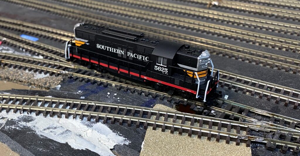
Kato to the rescue
Recording the progress of building the Denver’s RailRoads N Scale layout
All genuine posts are welcomed and will be acknowledged. Please submit your first post by email to: dennis@denversrailroads.com
Kato to the rescue
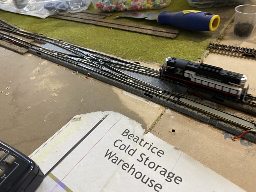
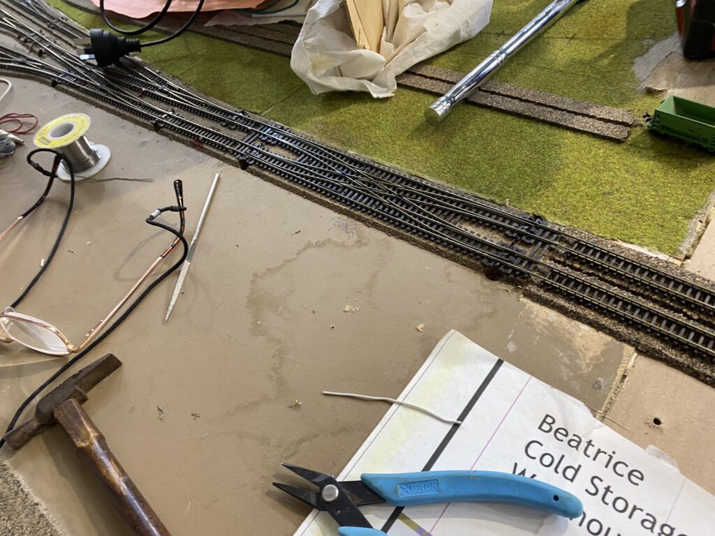
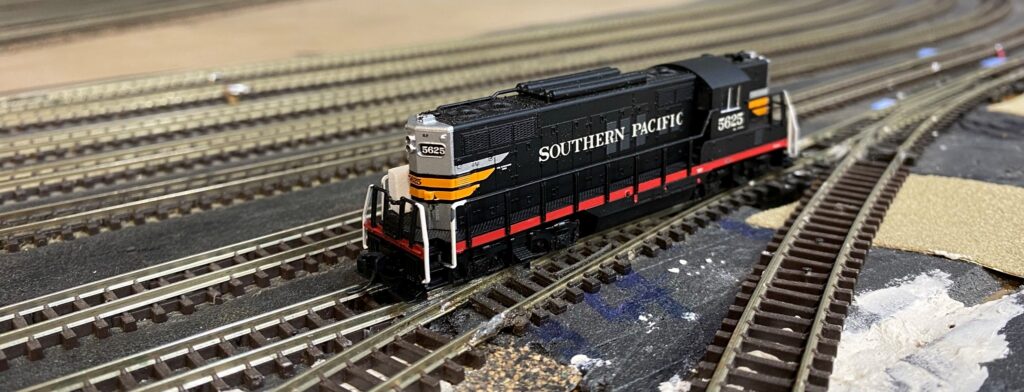
I finally got fed up trying to run trains at low speeds over the Peco scissors turnout and decided to replace it with a Kato unit. During the dismantling of the Peco unit I found one of the wires to one of the Dual Frog Juicers was broken. This was almost certainly the reason why Locos would not cross the Peco scissors at slow speeds without stalling. However I decided to continue with the swap as I saved 4 point motors and 2 dual frog juicers for future use. The Kato unit is a single point motor which throws the rails to either straight through, or crossed. How simple!
I did a few more jobs before Perth’s 40 degree plus Christmas drove me indoors! . . .
I Finally Close the Loop
After laying a temporary loop of track where Denver’s North Yard should be, I finally have a complete loop of track. I can now work on completing the industry tracks, and building kits and scenery, on modules 1 and 1a. I can then operate South Denver as a switching layout. There are nine industries including Denver Ice & Cold Storage, the Denver Market & Produce Terminal (Wazee Market), the PSC Arapahoe Power Station and the PSC Gas Works, American Manganese Steel foundry, Centennial School Supply, J.I. Case (a Farm Machinery Distributor), International Harvester Co and Thomas Williams, a coal dealer.
Then I can start work on finishing the track laying for modules 2 to 5 and building Denver Union Station and the C&S Rice Yard.
Almost there!
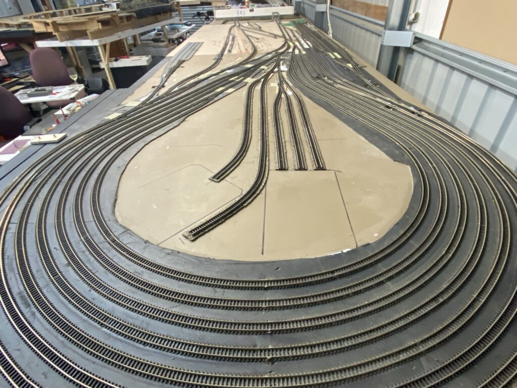
I have tested – and fixed up the track work – 6 of the 7 return loop tracks that form the Joint Line staging tracks. The 7th track only needs the installation of a frog juicer on one of the turnouts to be fully tested. By testing I mean the Atlas GP9 can successfully travel the length of the track, in both directions, without incidence. But only at speed step 12 (on my NCE Pro Cab) or greater at this stage. To move at really slow speeds will require cleaner track. And then I have to test the track with 10 or more freight cars backing thru the turnouts.
But for now speed step 12 is OK. I can now see if I can connect the two main lines running through Denver Union Station to the Joint Line Loop/South Denver module. And have power. Then it is on to the temporary return loop on Module 5.
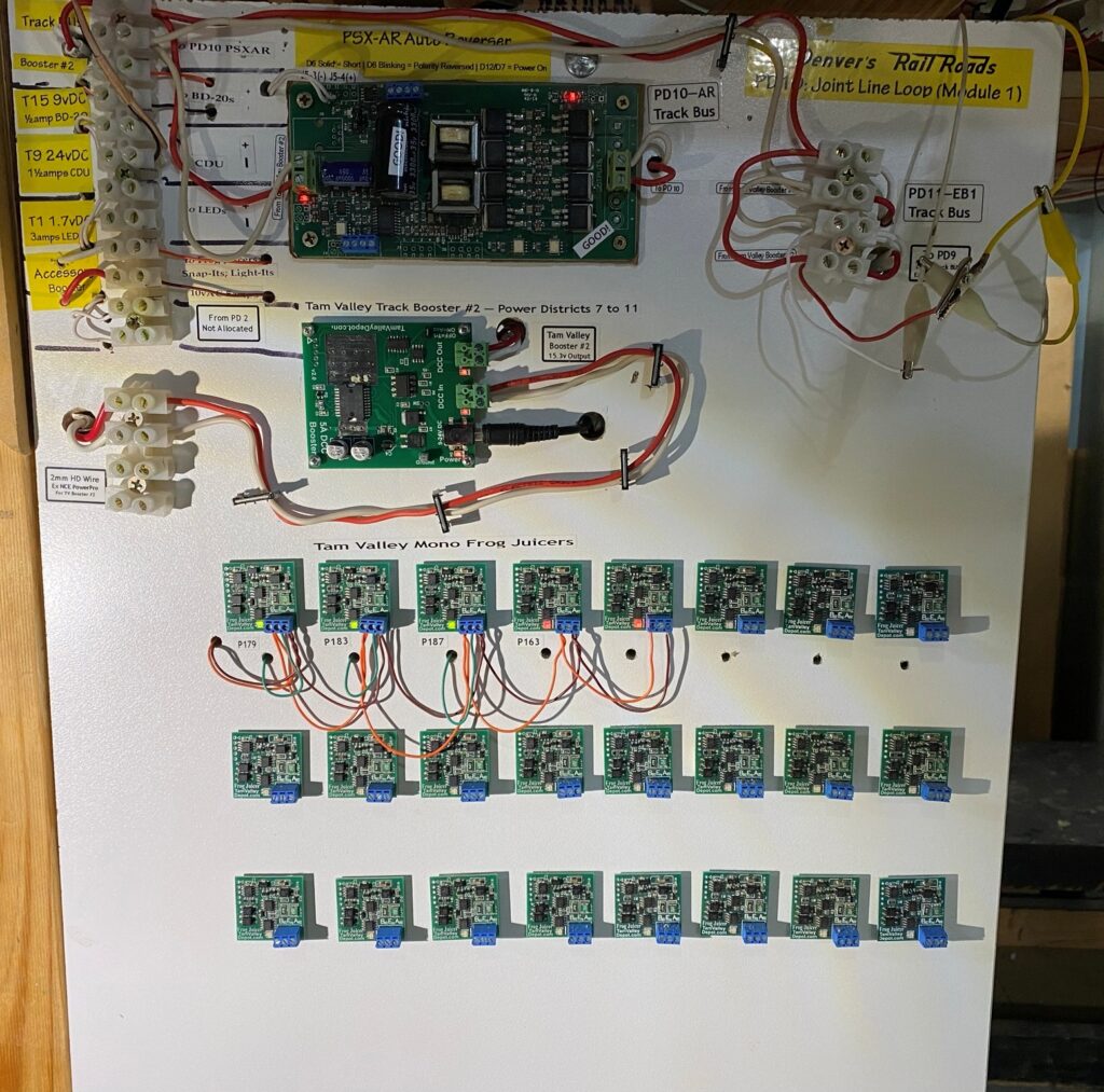
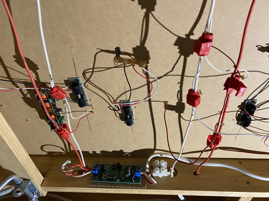
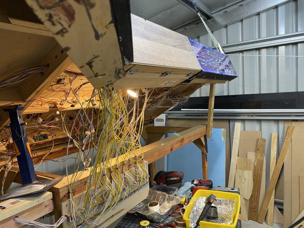
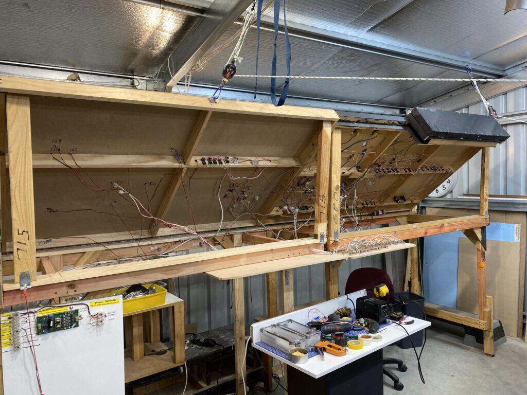
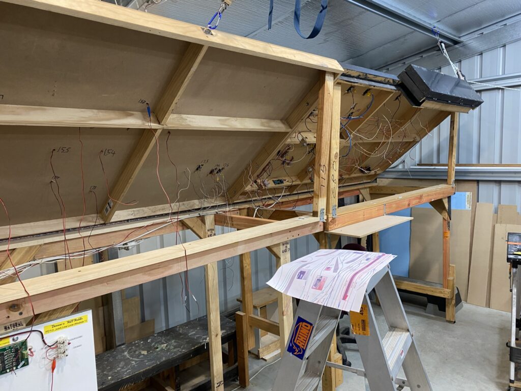
The Module Has Landed
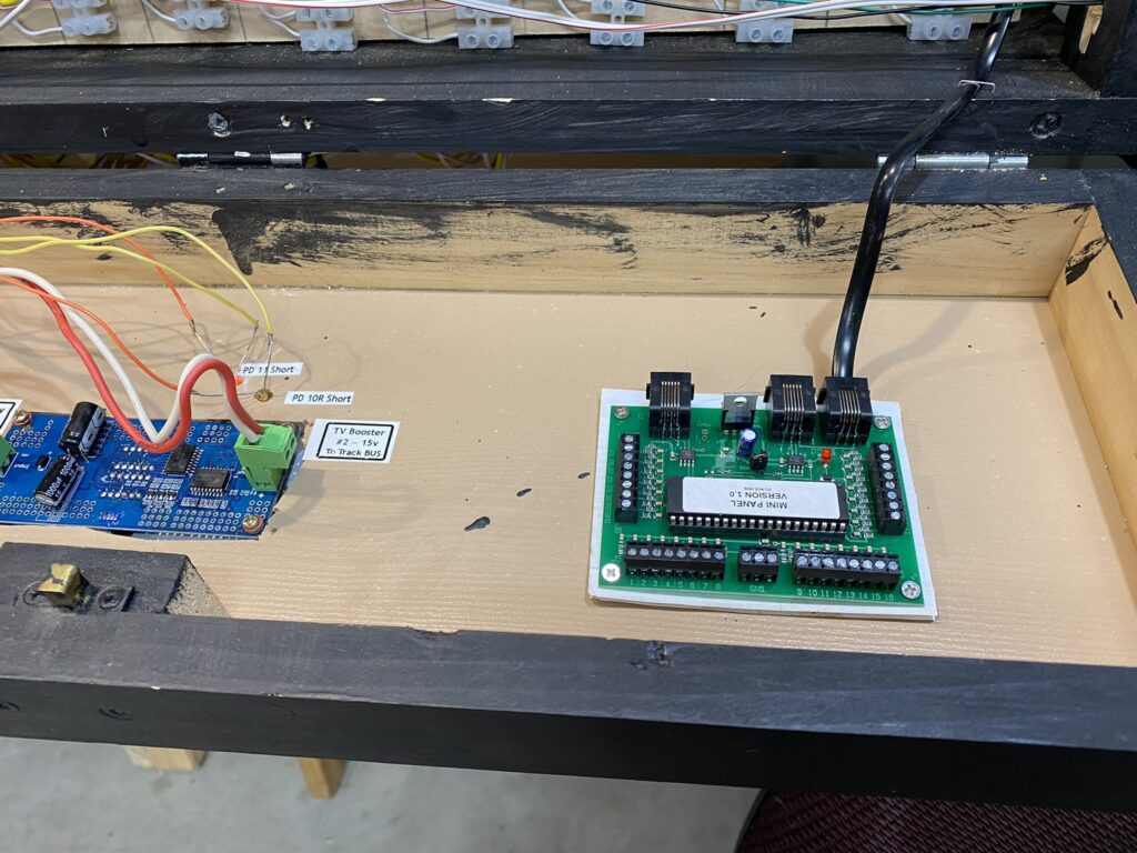
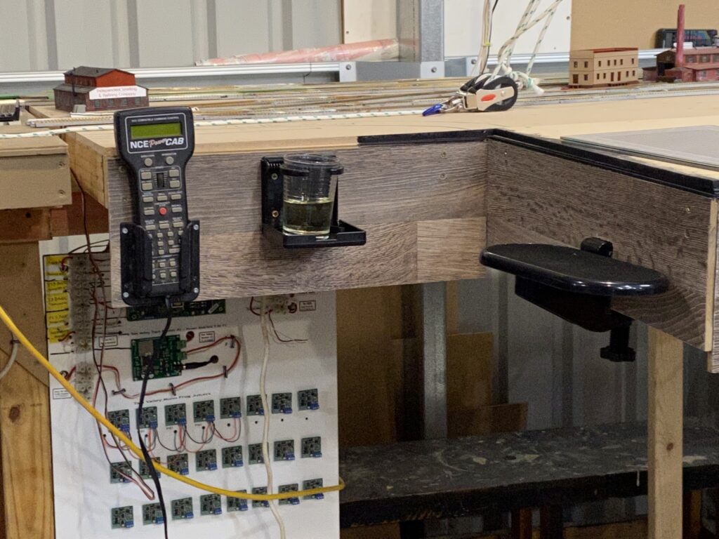
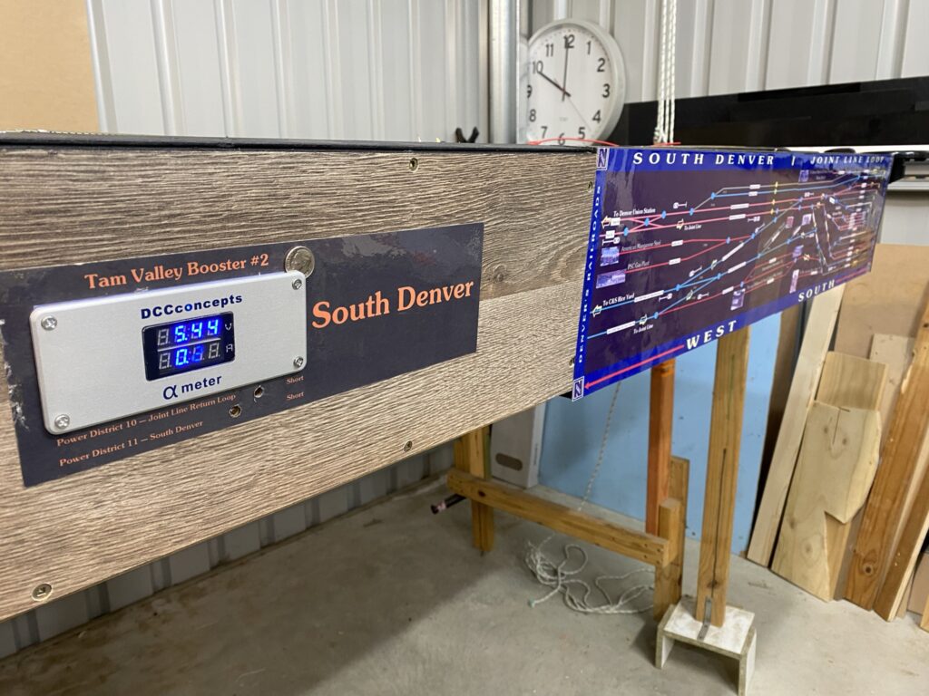
Finally, I have finished all of the wiring for my two end modules (#1 Joint Line Loop and #1A South Denver — also known as Power Districts 10 & 11), dropped the Modules down from their 45 degree height to zero, or flat, installed the DCC Concepts Alpha Panel (same as a RRamp meter) and wired up the short indicator LED’s. The next job is to actually run a Loco on the rails to find all of my wiring cock-ups. Then I can connect to the temporary loop on the other side of the Denver Union Terminal tracks and be able to run trains in a loop. This will allow me to speed match all of my Locomotives, while I run them in and look for issues.
Note the AML “Dime for Scale”.
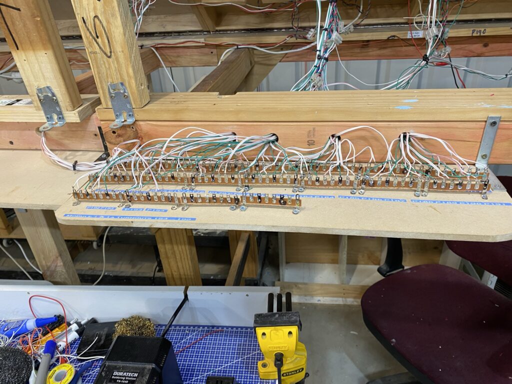
All waiting to be connected with the switches and LED’s on the control panel and the NCE Mini Panel.
Wiring Update
Getting closer to operating, or at least switching with my Proto-Throttle, this part of the layout.
How could I forget about shorts?
Well I did. In my defense it has been two years since I last had to spend hours looking for a short, but still! As you can guess I went ahead and wired up all my feeders to the BUS wires and then surprise surprise it no work. Still lacking a memory of shorts I unwired all the feeders and still had a short. After some time with a continuity tester I remembered that the frogs on all Peco Electrofrog turnouts needed to be gapped or insulated. I had done some, but not all. Anyway after using my Dremel cutting wheel to make the missing gaps, all the shorts went away and I can now start again. This time I will test with my RRamp meter after every connection that everything is still OK.
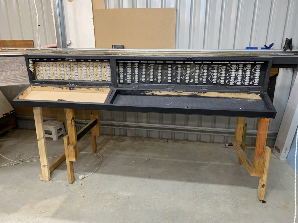
At least I have finished wiring the 40 turnouts to the front of the layout. Now all I have to do is connect a whole load of accessory decoders and design the control panel for the switches and lights. It is already built. Then comes the fun part — coding a NCE Mini Panel.
But first I have to get the track wiring organised and test run some Locos. That should be fun, I hope.
And the beat goes on . . .
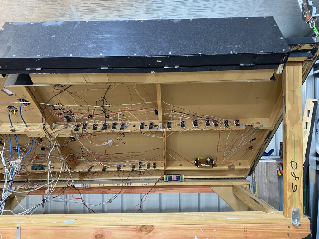
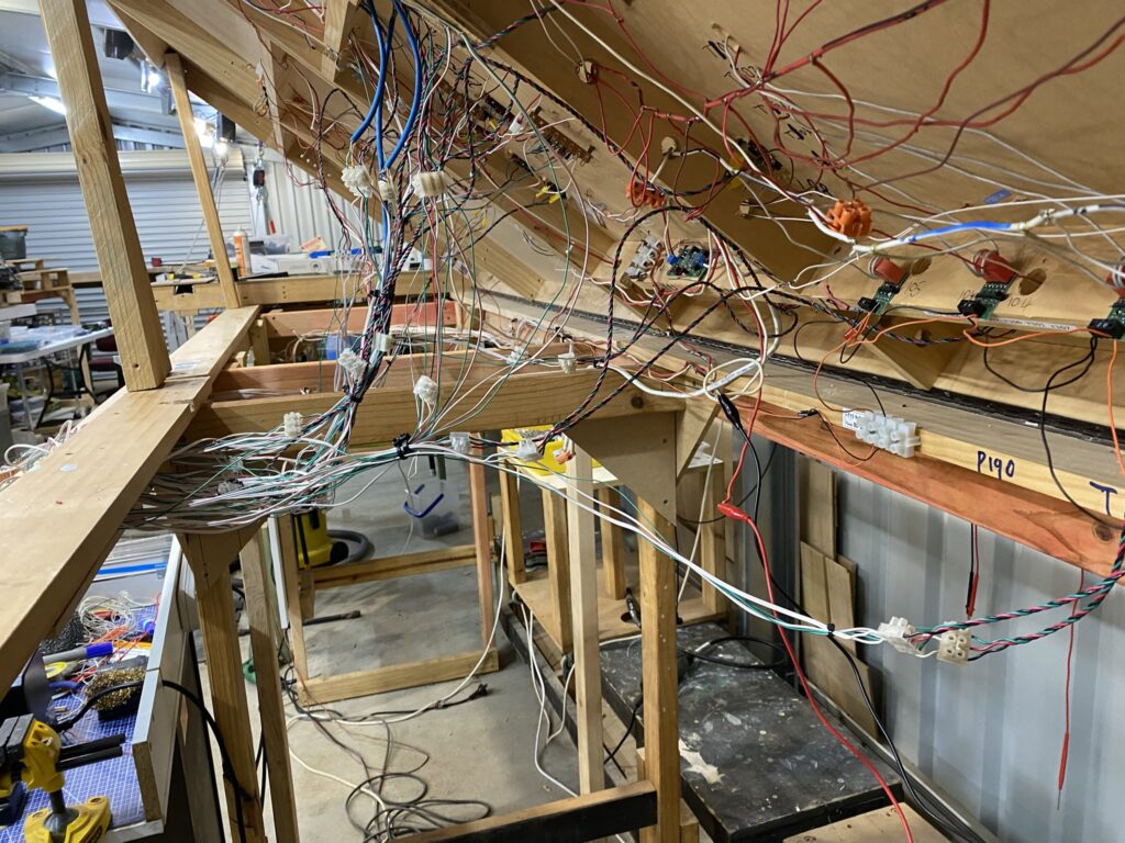
Donkey deep into wiring. I have 40 turnouts installed on just modules 1 & 1a and at least as many blocks requiring feeders and NCE BD-20 block detectors. Once all the block wiring and the accessory decoders are installed I plan to create a control panel with a diagram of the tracks and to install toggle switches and push-buttons to control the routes. The main line routes are going to be set using a NCE Mini Panel. For mainly economic reasons the industrial sidings, that do not require signalling, will use a central CDU (Capacitor Discharge Unit) and a diode matrix if necessary.
The following photos give an indication of where I am at with my wiring. Once finished I can start on building the industry kits and wiring up the temporary oval of track to enable test running and switching operations.
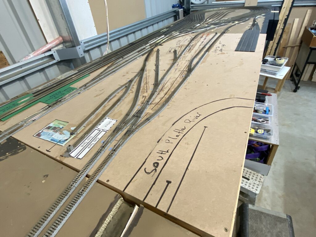
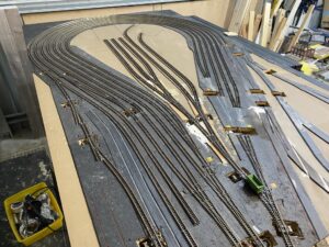
Finished tracklaying for Modules 1 & 1a (Power District 11)
It does not look much but there is a lot of complicated track laid in these two modules. I decided to scrap the Kato test layout as it had passed its usefulness days and I will shortly lay a temporary oval of track on Module 5 so that I can have a loop to test Locos. Consequently I have reused most of the Kato turnouts and straight track on Module 1a. Speedup the tracklaying considerably. I like the simplicity of Kato turnouts. I replaced a damaged PECO scissors crossing with a Kato and was amazed to find that Kato regard the unit as just ONE turnout with a couple of wires. The PECO scissors crossing required 4 point motors and 2 expensive frog juicers.
The challenge of course is to ballast the Kato track so that it blends in with the Peco track and is not obviously “toy” looking. If I can succeed I may well use more Kato turnouts in the future. I will elaborate on my immediate track laying plans and some significant changes to Phase II in a future blog.
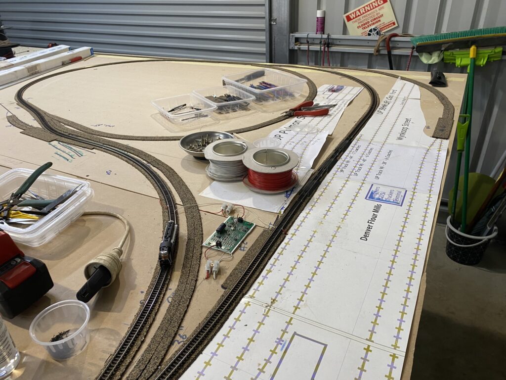
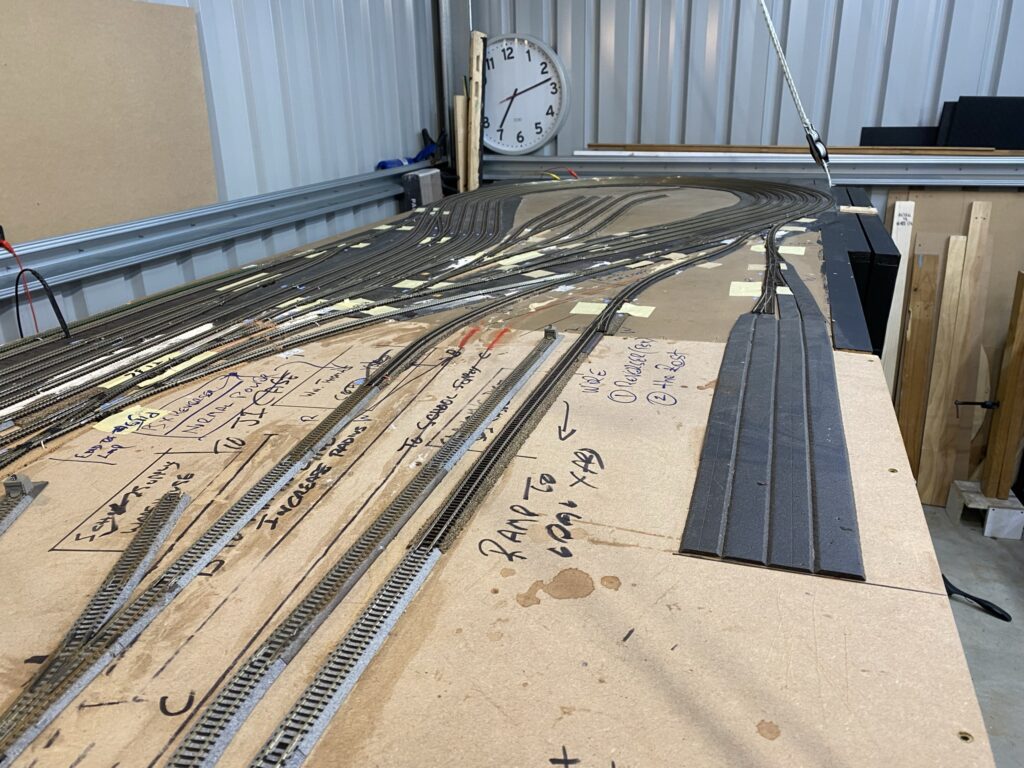
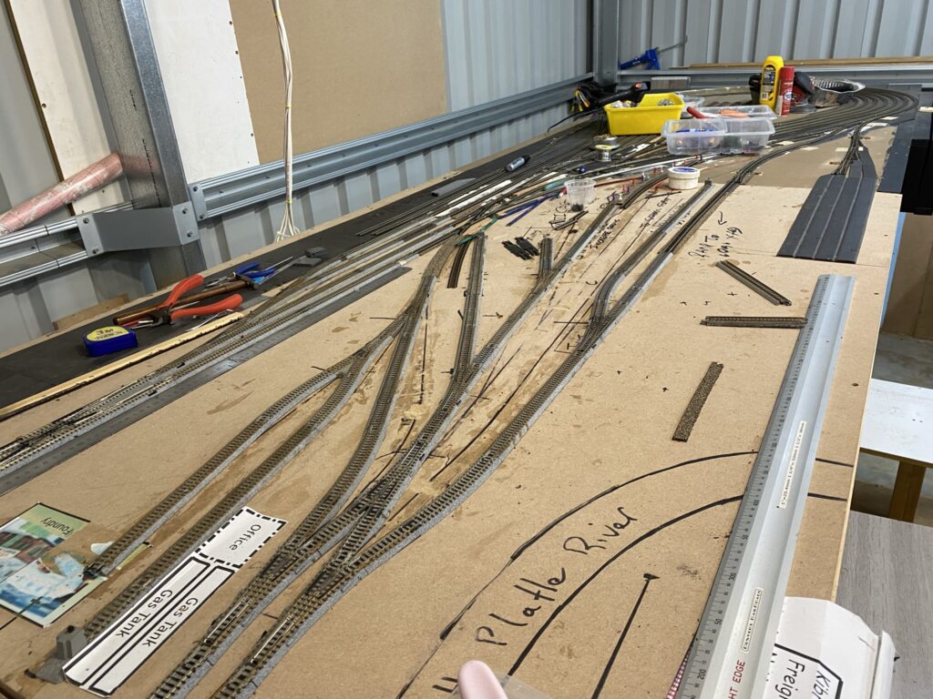
We have started to lay track at last . . .
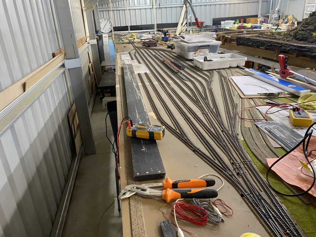
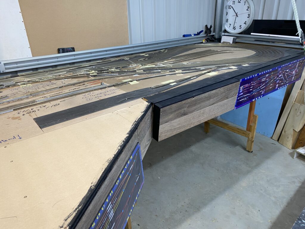
Just 10 turnouts left to install in module 1 and then its onto module 1a and the bridges in module 2. The track in the center of the photo is for the D&RGW Burnham Rail Yard & Shops. The track on the left leads to the Denver Market and the track on the right leads to various C&S industries and the branch line to the D&RGW Crested Butte Mine at Gunnison County.
The holes have already been cut but it takes awhile to install the turnouts because I am re-cycling them, using the turnouts that were installed in modules 5 & 6. I am also using re-cycled track for the sidings, but not the main lines were I am installing brand new Peco code 80 track.
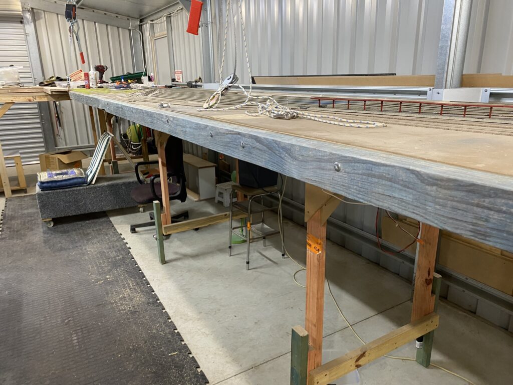
Ignoring all my tools covering module 1a the following photo shows modules 2 to 5 on the right and the Rio Grande Rocky Mountain area on the left. Initially only a temporary return loop will be installed between them. In time the loop will be converted to the Wye used to turn passenger trains so that they could back into Denver Union Terminal and a new D&RGW North Yard will be built.
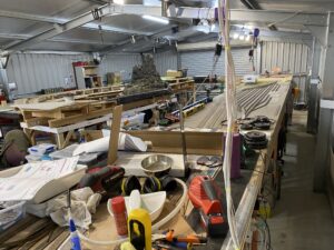
An overview of the entire layout can be found at https://denversrailroads.com/DPoverview.htm
Let’s get something finished . . . Continued
The current plan is to work only on modules 1 and 1a until they are both running well and scenic’d. Then to continue onto modules 2 to 5. This will include:
- Laying all the track and turnouts, including the addition of 2 more loops of track
- Wiring the track and turnouts to the control panel, including the installation of NCE SnapIt’s and LightIt’s
- Building the control panel, including the turnout controls and directional LED’s
- Installing working signals
- Wiring to a NCE Mini Panel using Macros to set up turnouts and signals for each of the 7 loops
- Cutting the South Platte River extension from module 2
- Tidying up the Cherry Creek river bed on module 2 and installing the bridges
- Extending the main line, wired to BUS stage only, through modules 2 to 5 to a temporary loop on module 5 for runaround loop testing
- Testing that all the tracks run well
- Building all of the kits (about 8 or more) planned for the modules
- Ballasting with the new Arizona Rock & Mineral ballast
- Adding the kits and low level grass and scenery
- Creating the Denver Market area south of the C&S 7th St area
- Building the front range mountains which will separate the Denver C&S 7th Street area from the Crested Butte Mine at Gunnison County
- Installing the kit for the Crested Butte Mine and attaching to the mountain scenery
Then I can finish laying the track on modules 2 to 5 (the DUT tracks are already laid) and install dozens of station platforms. But that is a job for another day! Unlikely to be this year.