Model Layout
Recording the progress of building the Denver’s RailRoads N Scale layout
All genuine posts are welcomed and will be acknowledged. Please submit your first post by email to: dennis@denversrailroads.com
Change of Direction . . . Let’s get something finished!
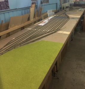
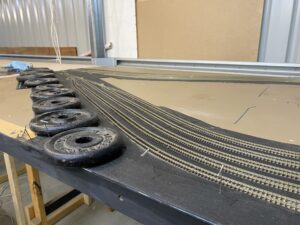
Rather than continue “putting the layout back together” which really means lots more carpenter jobs I have decided to start to build the entire layout starting with Module 1, which already has 5 loops of track installed for the Joint Line return loop.
I have already started to lay new roadbed. I prefer cork but I found that I had a lot of Woodland Scenics foam trackbed left over and as it had already been used in this module I have used both foam and cork.
To be continued . . .
Action Plan 1 – Dilemma: Track or Scenery
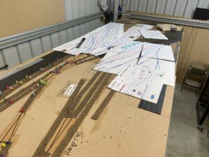
I have spent some time updating the track plan for phase 1. My current dilemma, which i cannot resolve before reinstalling the bench work, is should I lay all of the track in phase 1 first and then add buildings and scenery or should I move a module at a time.
The following is the track plan for just Modules 1-1a:
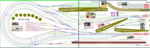
There is a lot of action in just those two modules. A dozen kits, some mountains and hills, a power station, an ice platform, less than car load platform loading, and a significant loco servicing area. By the time just these two modules are complete a lot of issues will have been resolved. The next 3 modules are pretty much oh hum in comparison.
Web Site Updated
STOP PRESS: I have updated the main web site with the new 3 phase construction plan and updated the track plan to reflect the extra one meter all around to the layout once the new garage is built. The action plan has been simplified as progress will be posted on this blog site, rather than on the main web site.
Re-organisation of Construction Phases
The following are the Construction Phases for 2020:
- Phase 1: Modules 1-5a – Joint Line Loop and Denver Union Terminal; CB&Q/D&RGW Coach Yards; UP & CB&Q 23rd St Shops; C&S Rice Yard; UP Wynkoop Street Branch and D&RGW Burnham Shops
- Phase 2: Modules 5b-9 – Main Line from Salt Lake City Loop to Utah Jct. & East Denver Belt Line; D&RGW North Yard & Industries; UP 36th Yard
- Phase 3: Modules 10-12 – Coors Brewery Branch, Glenwood Springs Industrial District and D&RGW Moffat Line & Craig Branch
I will be updating the information on the main web site as time permits.
13m x 7m (42′ x 23′) Garage Plans submitted for Council Approval
We have today submitted plans to our local council in Western Australia to build a 13m x 7m (42′ x 23′) Garage to house the Denver’s RailRoads layout. If approved I can set up the old Denver’s RailRoads layout, which measured 12m x 6m, without any changes to the basic plan. However the extra one meter (39″) to both the length and width means that I can make the following enhancements to the layout:
- The redesign of the tracks entering Denver Union Terminal Station (DUT) from the North and East including the Wye used to turn passenger trains so that they could back in to the station.
- The addition of the Union Pacific 36th Street yard and the Pullman yard.
- Widening the aisle width between module 12 and module 3 from 1.3 feet to 4.3 feet.
Life is full of changes
For the last eight months or so our house has been up for sale and finally it sold late in 2019. My wife wanted to move to a colder, less humid, climate and we agreed on Mandurah, just south of Perth in Western Australia, where I have family (and help lifting layout modules). As part of our negotiations it was agreed that we would buy a house and land big enough to house my 12m x 6m layout as is. That was easier said than done but we have now purchased a 1991 square meter block of land which according to the Mandurah city councils web site should mean that I can build a 13m x 7m garage, not only large enough to house the old layout but also large enough to allow me to extend the layout where it needs it (in the Denver freight yard) and to increase the width of the center aisle.
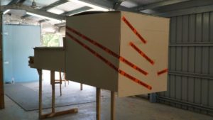
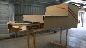
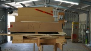
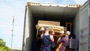
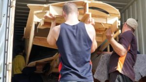
The following photos are of the removal of the “mountain” module (Gore Canyon) from my garage and into the 20′ container. There were 8 modules in total loaded into the containers. Only this module and one other are without legs. Both are inner modules that do not form part of the continuous run around the outside. So it should be fairly quick and “easy” to reconnect the modules that run around the outside and have an operating layout. The inner modules can be added at a later date.
View from the back.
View from the side.
View from the front before we realised that to get it into the container with a minimum of fuss we would need to take the legs off.
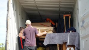
Legless module going up the ramp and into the container
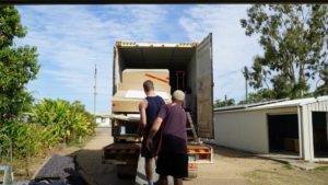
A bit more in.
And more.
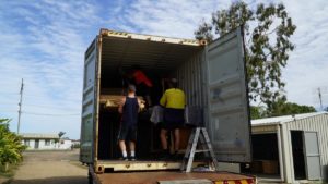
And even more.
And finally into the container. Now we have to start thinking about getting it out and back on to it’s legs!
Test Track Conclusions
A little while ago I decided to build a 6′ x 2’6″ N Scale test track. The following are my initial observations.
The primary objective was to be able to test run locomotives and cars in a continuous circle and to change the DCC loco code from the default of “3” to the loco road number.
There were many secondary objectives including:
- Testing Kato turnouts and track
- Testing DCC Concepts ADS solenoid accessory decoders and NCE Snap-It decoders
- Testing NCE BD-20 track detectors and Team Digital DBD22 track detectors
- Finding the appropriate use for NCEs AUI-01 and the Mini Panel systems
- Using JMRI Panel Pro and Decoder Pro
- Using the program “Train Controller” from Freiwald Software
- Finding the best method of wiring the layout. ie:
- Using Tortoise or Servo motors and JMRI
- Using solenoid motors with DCC Concepts ADS or Snap-It accessory decoders and JMRI
- Using single CDUs (Capacitor Discharge Unit) to power large numbers of solenoid motors and Gaugemaster GM500 latching relays to activate signals and light LEDs to indicate turnout positions.
- Last, but by no means least, finding the easiest method of signaling the layout.
As my NCE Power Pro Radio system was wired to the main layout I used my backup NCE Power Cab system to run the test layout.
Initial conclusions:
- The motors in the Kato turnouts are polarity driven with only two wires – quite different to the 3 wire solenoid Peco point motors.
- The NCE Power Cab is very under-powered at 1.8 volts and about 1.8 amps.
- Start up amp usage was around .31 amps.
- The DCC Concepts ADS solenoid accessory decoders did not work as expected with the NCE Power Cab. Only 4 of the 8 operated correctly. The start up amp usage of the NCE Power Cab jumped to 1.33 amps.
- Consequently I had to use NCE Snap-Its to power the turnouts (using a DCC Concepts DCD-SDC adapter to convert the 3 wires to 2 wires for the Kato turnouts).
- The Snap-Its worked fine but did not have the additional SPST connections that the DCC Concepts ADS units have. However apparently they can connect to NCEs “Dual Relays” and maybe other relays. To be tested.
- JMRI failed to function after the first couple of screens. No idea why but I suspect that the RS232 connection of Power Pro is much stronger than the USB connection of the Power Cab. However I need Decoder Pro to work so I will persist with using JMRI. Otherwise I will have to use the RS232 connection of Power Pro on the main layout.
- The test version of “Train Controller” only works for 15 minutes which is not enough time to determine if it works ok.
- I was keen to use the Gaugemaster GM500 latching relay to indicate the turnout position. However with the Snap-It and the two wire Kato turnout I could not identify the correct connections. I know that these relays work fine with Peco point motors.
- The Team Digital DBD22 track detector worked fine – except that no matter how I wired it I could not get an external LED to light. The internal LEDs on the BDB board worked correctly. Consequently I replaced it with two NCE BD-20s and I will not be buying any more DBD22s!
- It would appear that using the AIU-01 with a Power Cab system is questionable. The AIU is only really of use with JMRI so that test can wait until the main layout is ready.
- There seems no point testing the NCE Mini Panel with such a small layout.
- The layout is inappropriate for testing Signal Systems.
As a result of the above I only intend to use the Kato layout for its primary purpose of test running locomotives and cars in a continuous circle and to change the DCC loco code from the default of “3” to the loco road number.
However I may well add scenery and make the layout into a display layout. There are two industry tracks, a two track yard and a railway station track. There are plenty of shunting options and for the future it could be used to test the “Ship It” system. Allowance has also been made for a Wye track so as locos can be turned.
With regard to the best method of operating a layout in terms of turnouts, block occupation and signals, there seems to be 3 options:
- Use Tortoise or Servo motors for turnouts and connect to JMRI Panel Pro – the problem I have here is that Tortoise are (a) very expensive, (b) too large to install on an N scale layout and (c) have to be installed from beneath the layout, unlike Peco motors which attach to the turnout when installed from above. Apart from the reservations listed I have a large number of Peco and SEEP solenoid motors in stock already.
- Use solenoid motors with either NCE Snap-Its or DCC Concepts ADS decoders. The problem here is that (a) I keep hitting snags and problems, (b) every turnout requires its own CDU making it VERY EXPENSIVE and increasing the wiring significantly and the system does not work well with latching relays, which I hope to use for signals.
- What might be called an ANALOGUE SYSTEM:
- Use one (or more) large 24-32 volt CDU’s to throw all of the turnouts.
- Use Gaugemaster GM500 latching relays to indicate turnout position.
- Use GM500s and BD-20s to activate signals.
- Use a diode matrix for route control.
- Use local control panels to indicate train operation.
Since starting to write this blog I have spent a lot of time on Google and YouTube investigating Signal Systems. Most either require JMRI, Arduino scripts, infra-red track detection (I only want to use Current Sensing devices like NCEs BD-20) or very complicated DIY designs. I have also noted that at least two (Team Digital and Iowa Scaled Engineering) Signal Systems which showed promise, in terms of what I am looking, for had discontinued their products.
However Circuitron (of Tortoise fame) appear to have circuit boards that might fit my requirements, which are simply to be able to change 3 colour signals using BD-20 block detectors and either Gaugemaster GM500 latching relays or standard relays. Consequently I have ordered the following Circuitron products:
- SD-1 Signal Driver
- ER-1 External Relay
- BD-2 Block Occupancy Detector
Once these products arrive I will be able to test them to see if they perform the Signaling functions I am hoping for. We shall see.
Phase II Trackwork FINISHED !!
OK. All of the track laying for phase II is finished, which is a good thing given that I only have a dozen pieces of flex-track left.
I am now deep into the wiring of the motors in Denvers yards (what was phase four) while John is finishing installing SEEP point motors on the main line past the East Denver Belt line leading into Denver’s yards from Glenwood Springs (the old phase two).
Once we have all of the point motors wired up we can concentrate on the BUS wiring, which is complicated in Denvers yards as there is a return loop which will require a PSX reversing unit.
Phase II . . . Only 6 tracks left to lay
Finished installing the last of the turnouts in D&RGWs North Yard last night. Only have the 4 service tracks and 2 industry tracks left to lay.
Then it is onto wiring, wiring and a lot more wiring. Model RailRoading is fun! Still I am looking forward to constructing the control panels. Best part (together with scenery) of the hobby for me.
New areas to explore include controlling main line turnouts via DCC and installing signals. I found a really nice 3 light Chinese made N Scale signal (3 pack) at Amazon for only $11AUD each. Normally N Scale signals cost around $30 each so I have 27 more in transit to me. Plus I have 20 Drawf N Scale Signals (in packs of 10) coming for installation at DUT as part of Phase III.
Phase III Update
Thanks to the hard work of Rod and John all of the Denver Union Terminal (DUT) tracks have been laid and SEEP turnout motors have been installed – wired and tested – under the baseboard. Now onto the laying of the tracks for C&S’s Rice Yard and the passenger coach yards.