Another Mid July Update on the Rock Island Sandown N Scale Layout
Recording the progress of building the Denver’s RailRoads N Scale layout
All genuine posts are welcomed and will be acknowledged. Please submit your first post by email to: dennis@denversrailroads.com
Another Mid July Update on the Rock Island Sandown N Scale Layout
I have made quite good progress over the last 8 days . . .
First I glued 2′ (50mm) foam all around the left side and rear of the layout where I wanted a grade separation between the tracks.
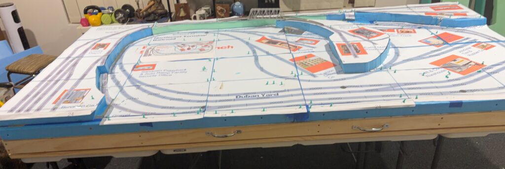
Next I laid all of the Kato Unitrack on lower part of the layout. This included confirming that the reverse loop was in fact a viable option.
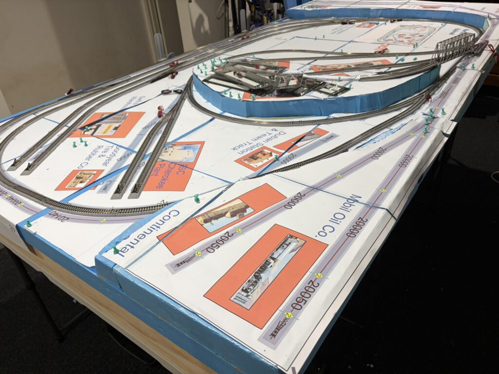
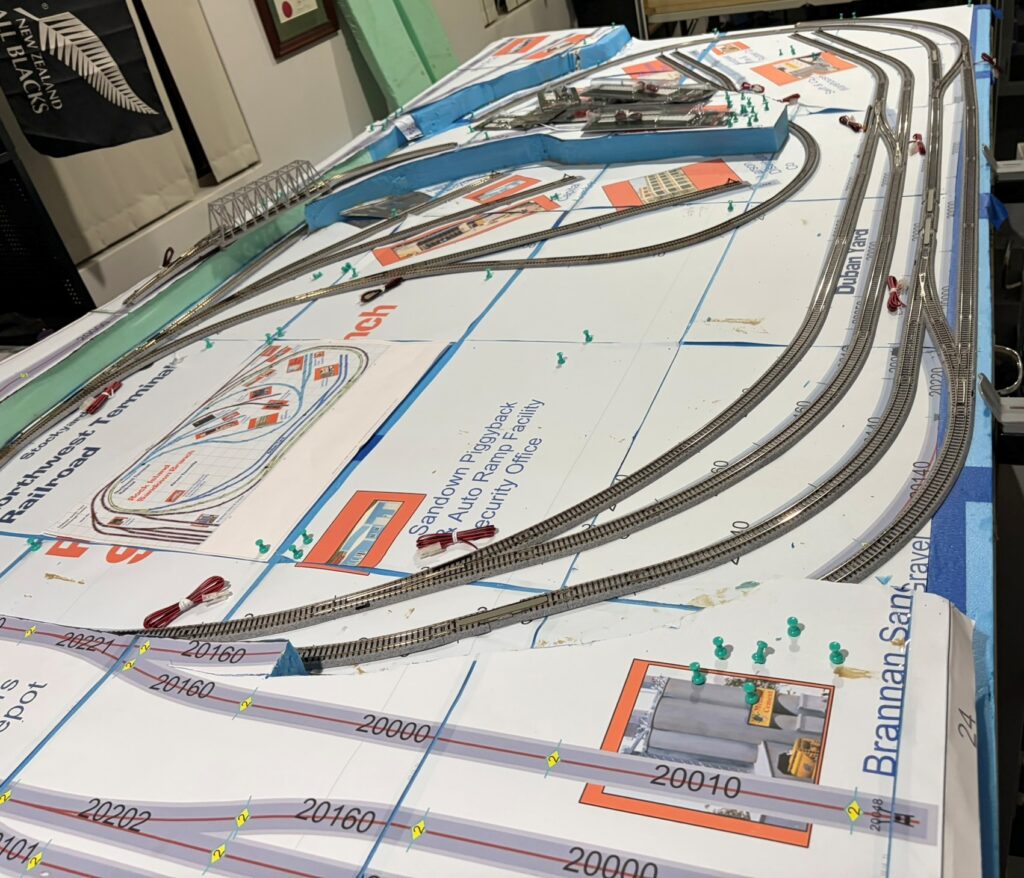
Then I tested the DCC connection to the trackage, at first with a RRamp meter and then with an Atlas U36B locomotive. I connected an NCE PowerCab to the end of one of the sidings and then checked the voltage on every branch, first making sure that the Kato #6 turnouts were pointing in the correct direction for the power routing. The loco ran at a slow speed (30/126) on every piece of track with no stalling or challenges.
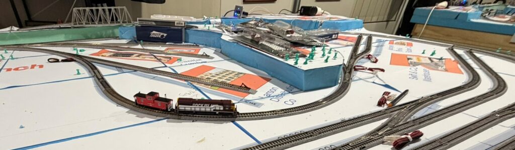
Yesterday I finally took delivery of a Woodland Scenics 2% incline/decline set. Although made with white foam, aka Expanded Polystyrene (EPS), which is not easy to work with, as compared to the blue Extruded Polystyrene (XPS), the Woodland Scenics product is wonderful for the determination of the correct percentage incline required on a layout.
Upon installing the incline set it quickly became apparent that I needed a longer run to reach the 2″ height of the scenery I had planned for the upper level of the layout. Furthermore the foam on which the oil and bakery industries planned for the right hand corner of the layout needed to be reduced in height from 2″ to 1½” and in order for the left side trackage to gain the 2″ elevation required to meet the right hand side trackage the incline would have to be 3%.
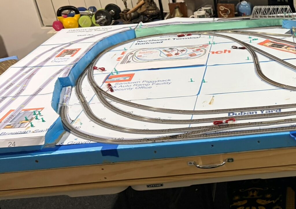
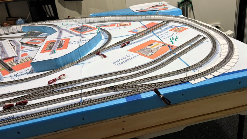
Now I wait for the Woodland Scenics 3% incline/decline set to arrive to finalise the track arrangement.
Mid July Update on the Rock Island Sandown N Scale Layout
I have made reasonable progress over the last 7 days while surviving the last round of Chemo prior to the operation to remove the tumour.
First I installed the 50mm foam insulation on top of the plywood base. Not as easy as it sounds as the foam sheets are only available in a 4′ x 2′ (1200mm x 600mm) size, which meant gluing 4 full size sheets plus cutting 4 strips of foam to equal the slightly larger 8′ x 4′ frame. I used Selleys “Liquid Nails Fast Grab” which did a pretty good job. I also found that long screws were able to hold the narrow strips of foam at the front to the main sheets.
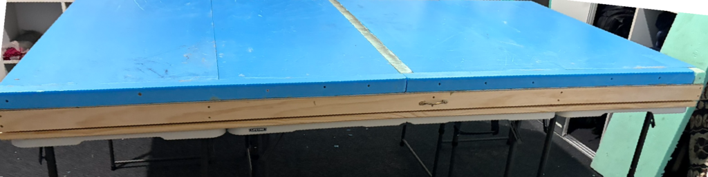
I then used masking tape to seal the gaps. I was concerned about how level the layout was but on checking with my digital spirit level I found that there was only about a ½% difference all round.
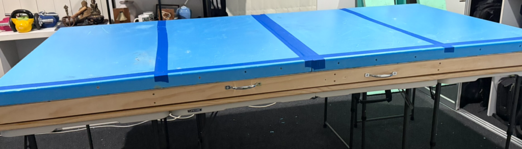
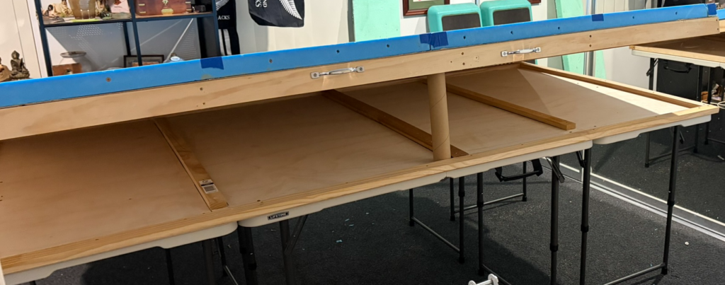
Although now a little heaver the layout can still be raised to allow access to the wiring while standing up.
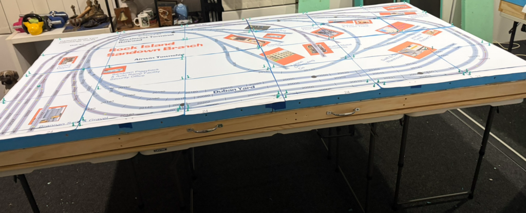
I then printed the entire track plan using AnyRail ver. 7 on a 1:1 basis. This resulted in 30 A3 (11.69 × 16.54 inches) sheets of paper which I laid out on top of the foam. As expected the actual layout is a little larger than the drawn track plan which will give me some flexibility when it comes to positioning the actual track.
AnyRail ver. 7 also provides a “List of Materials” which includes all of the individual Kato Unitrack pieces required. I have ordered these from Plaza Japan and expect delivery during the next 7 days. As an indication for new Railroad modelers the cost of purchasing all of the Kato Unitrack and turnouts for the layout was just over AUD$1,000. Keep in mind that the cost of Kato turnouts includes the point motors, making Kato half the price of an equivalent Peco turnout.
My decision to use Kato track, rather than Peco, was: (a) ease of track laying; (b) Kato track is bullet proof; (c) no need to source Mid-west cork roadbed (which is very expensive to ship from the USA) and (d) flexibility in the different curve radii used.
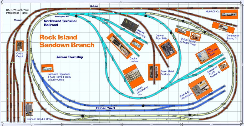
A major advantage of laying out the 1:1 track plan is the ability to plan where the scenery will be developed. The current plan is to raise the track on the outer loop at the back of the layout and the North Yard trackage (shown with brown lines in the following track plan) around 2″ (50mm) higher than the track in the main body of the layout (shown with cyan lines). I am using the 1:1 track plan to create templates for cutting the 50mm foam to fit. However I cannot complete this process until the Woodland Scenics 2″ risers arrive from Lombard Hobbies at the end of the month.
The branch trackage to the Denver Flour Mills and Eaton Metal Products is also 2″ higher than the Northwest Terminal Railroad trackage. Achieving this will be challenging, as will the positioning of track and scenery in the Duban Station area. I may abandon the Station and Team track spur in favour of the easier laying of scenery. We shall see.
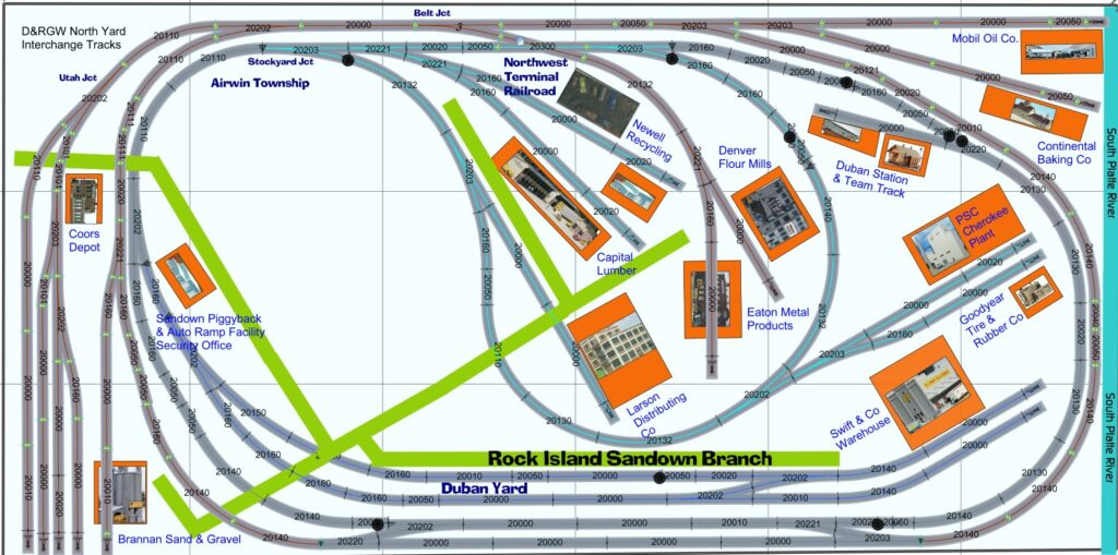
I have began to sketch out the scenery on the latest edition of the track plan (as at 13th July 2026). The green lines are roads and the cyan strip indicates the path of the South Platte River which flowed to the east of the Public Service of Colorado Cherokee Power Plant.
Progress continues on the Rock Island Sandown N Scale Layout
Last night I was able to finish building the layout to”flip top” stage. i.e. you can raise the whole layout up at an angle and work on the underside wiring whilst still standing up!!
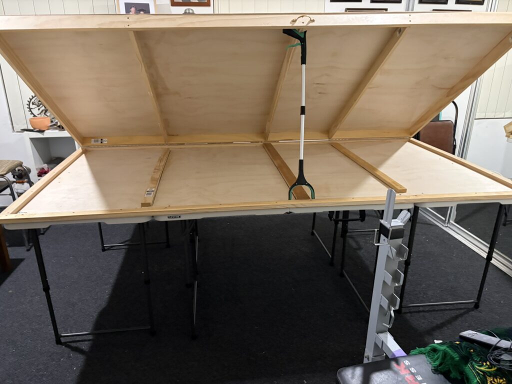
Now all I have to do is glue the 50mm foam insulation to the plywood top and I will be ready to lay track and scenery.
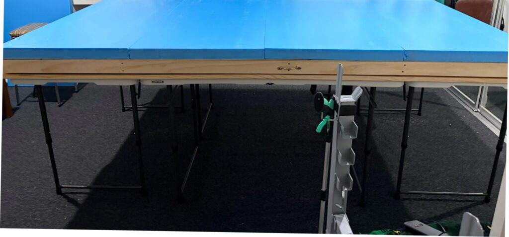
Opps . . . Hinges were on the wrong way around
On testing the hinged support (with a minimum number of screws) for the Rock Island Sandown N Scale Layout I realised that I had placed the hinges on the wrong way around and that I needed them to allow the layout to be lifted from the front.
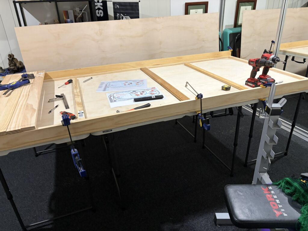
This photograph does not look as if much has changed overnight but given the extreme Chemotherapy-Induced Neuropathy (a condition that happens when certain cancer treatments affect the nerves that carry signals between the brain, spinal cord, and the rest of your body — especially in the hands and feet) in my fingers I did a pretty good job of installing 3 piano hinges with very small screws on the back support.
Having fixed that screwup I now only have to cut the support braces to size and attach them to the front and back layout supports. I am then good to go with the second sheet of 8′ x 4′ plywood as a base for the 50mm insulation foam board. I am finding that in spite of the difficulty of using my fingers I am greatly motivated by achieving the continuing layout build each night.
Early July Update . . . Started building the Rock Island Sandown N Scale Layout in the house
Thanks to the side effects for my regular Chemo sessions for Oesophagus Cancer I am unable to continue working on my large Denver’s RailRoads which is located in an external 4 car garage.
However rather than just dream about running trains again I decided to take advantage of now being alone in a 4 bedroom house with no one to object to how much space my model railroading takes up. So as detailed in my earlier blogs and on Facebook, I have started building a 8′ x 4′ N scale layout in what was my wife’s gym.
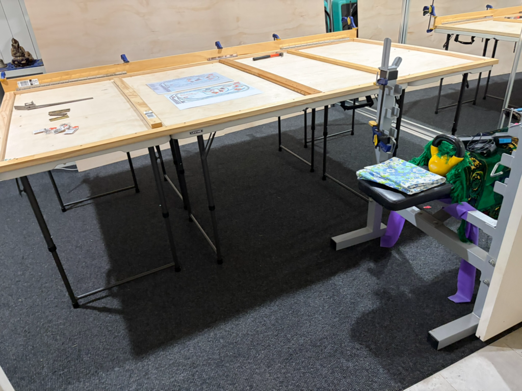
Because of my poor physical health I have had to be careful to plan the building of the layout with lighter materials than I would normally use. Consequently I have used four outdoor type tables from our local hardware store as the base, bound together by a 3mm sheet of 8′ x 4′ plywood, suitably braced, as the following photograph shows. I now plan to attach a second 3mm sheet of 8′ x 4′ plywood, hinged to the lower piece, so that I can work on the underside wiring whilst standing up.
The track for the layout will be laid on top of 50mm insulation foam board which will be glued to the second 3mm sheet of 8′ x 4′ plywood, hopefully making a strong but fairly light weight layout. We shall see. The ultimate rail height from the floor will be just over 34″ which should be quite a good working height in the circumstances.
I keep fiddling with the track plan and hopefully improving the layout. The following is the latest rendition (as at July 5, 2026) which includes an additional spur on the Northwest Terminal Railroad (showing in cyan below). I have also changed a couple of Walthers kits representing various prototype buildings. The PSC Cherokee Plant is now the major industry on the layout.